 skemyOpen Skemy
 Design AV schematics people can follow.
Design AV schematics with devices, ports and connections. Organise HDMI, fibre, audio and network signals and prepare system documentation.
From sources to destinations
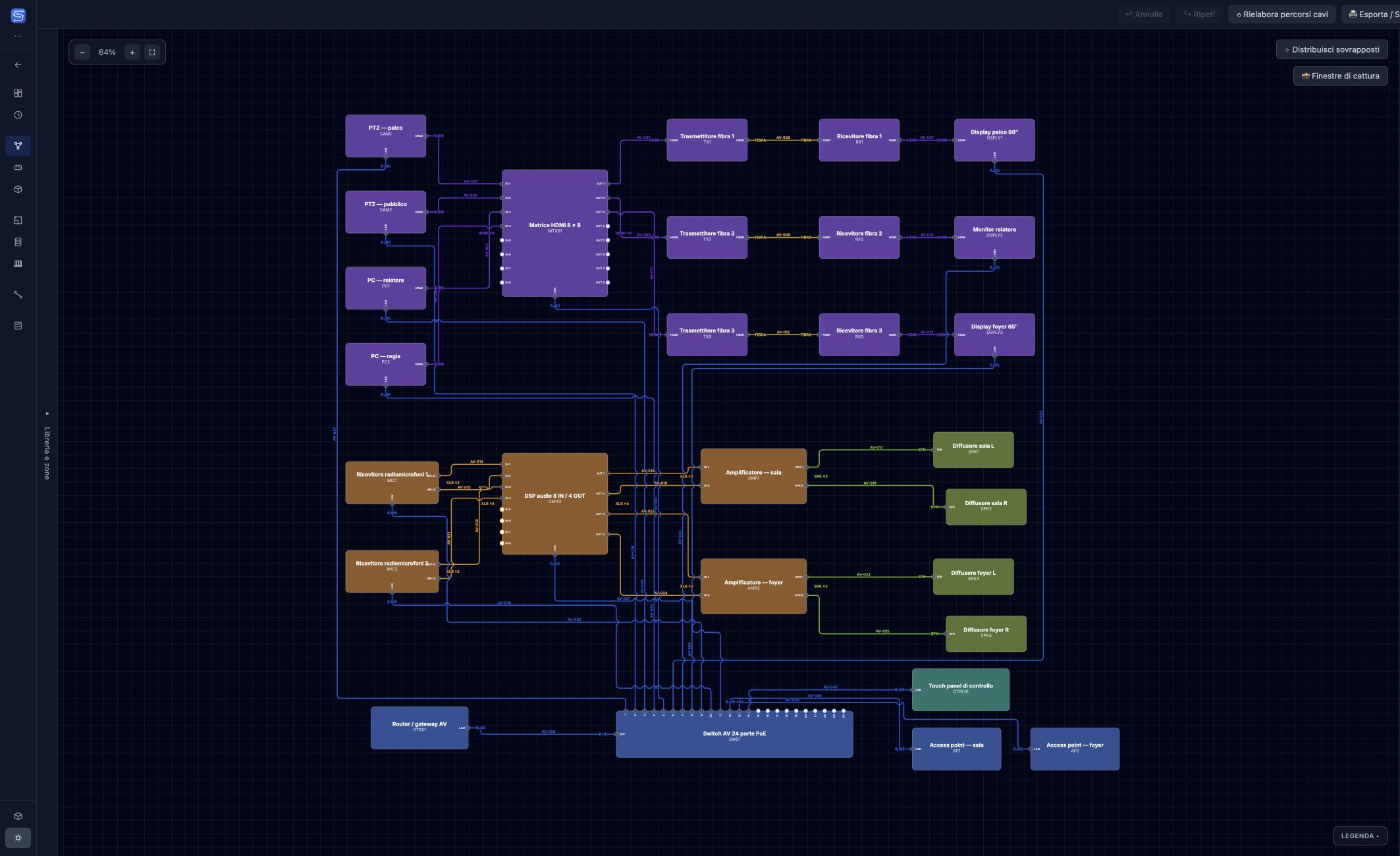
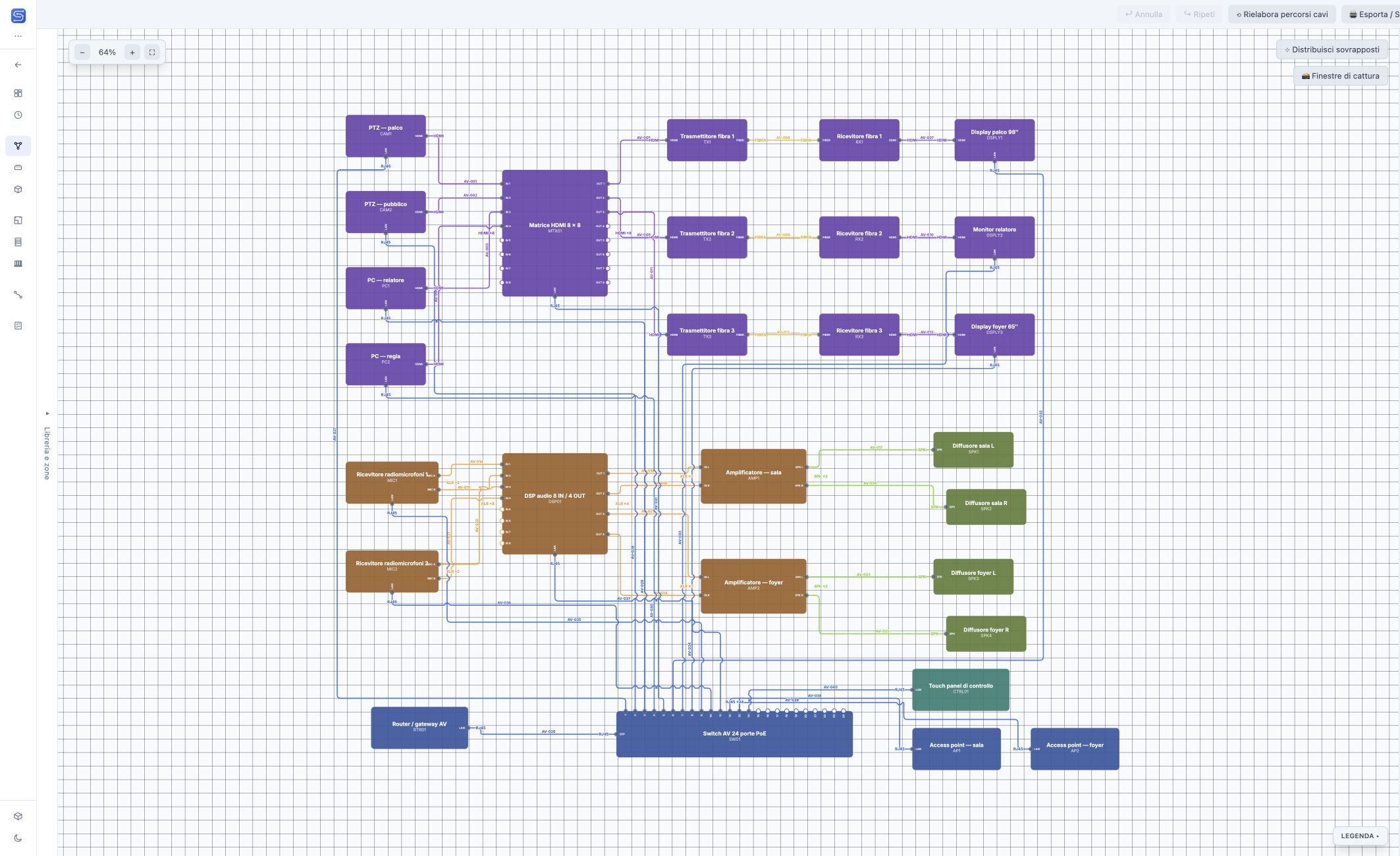
An AV system brings together signal sources, processing and distribution. In System Schematic, connect device ports to describe these relationships: a camera to a matrix switcher, a fibre transmitter to a receiver, or a DSP to amplifiers. Each connection keeps its signal type and cable identifier.
A conference room, control room and foyer
The demo contains 28 devices and 40 connections across three spaces. A matrix switcher distributes video to the displays, a DSP and amplifiers handle audio, and a switch connects the AV network. Compare the interface themes to explore the view.
Keep a growing project organised
Floors and zones help you select the spaces to display. The schematic arrangement describes how the system works; the floor plan describes where devices are physically installed. Work on both without mixing the two arrangements.
Drawings to print
Print or export to PDF the current view, selected zones or every zone, with a title block for project, client, designer, revision and date. Vector parts of the drawings stay sharp when enlarged, and DXF export is also available.
In the same project
The schematic is where devices and connections are created. The same connections are the rows of the Cable Schedule and the occupied ports in I/O Mapping; the same devices appear in the rack and on the floor plan. There are no separate files to reconcile: change a connection once and every view that shows it reads it from the project.