 skemyOpen Skemy
 Place devices and cables on the floor plan.
Place devices on floor plans, import DWG, DXF, PDF and images, calibrate scale and organise cable routes, floors and zones.
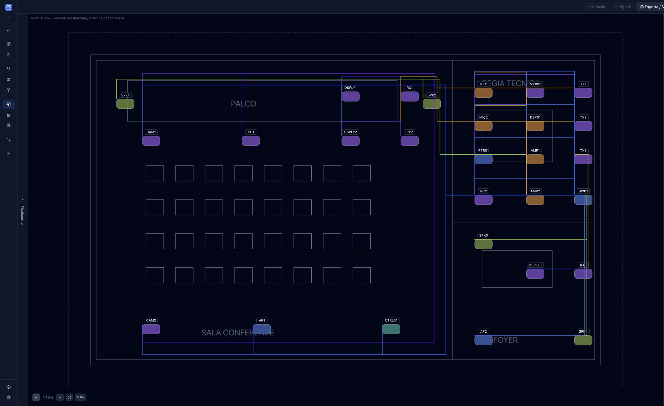
A physical view of the system
Device Layout connects project logic to installation spaces. Place devices on the floor plan and organise work by floors and zones. Physical positions are separate from the System Schematic arrangement, so you can keep the schematic readable while representing the spaces.
Import DWG, DXF, PDF and images
Start with DWG and DXF drawings, PDF documents, SVG files or PNG and JPG images. Select PDF pages and manage layer visibility and colours in vector drawings. DWG import uses background conversion with the project saved in the cloud. Wait for completion and check the result.
Calibrate before measuring
Crop the useful area and calibrate the scale with a known distance. Check proportions and imported layers before measuring: compatibility depends on the source file contents. A calibrated floor plan provides a basis for placing devices and assessing distances.
Follow physical cable routes
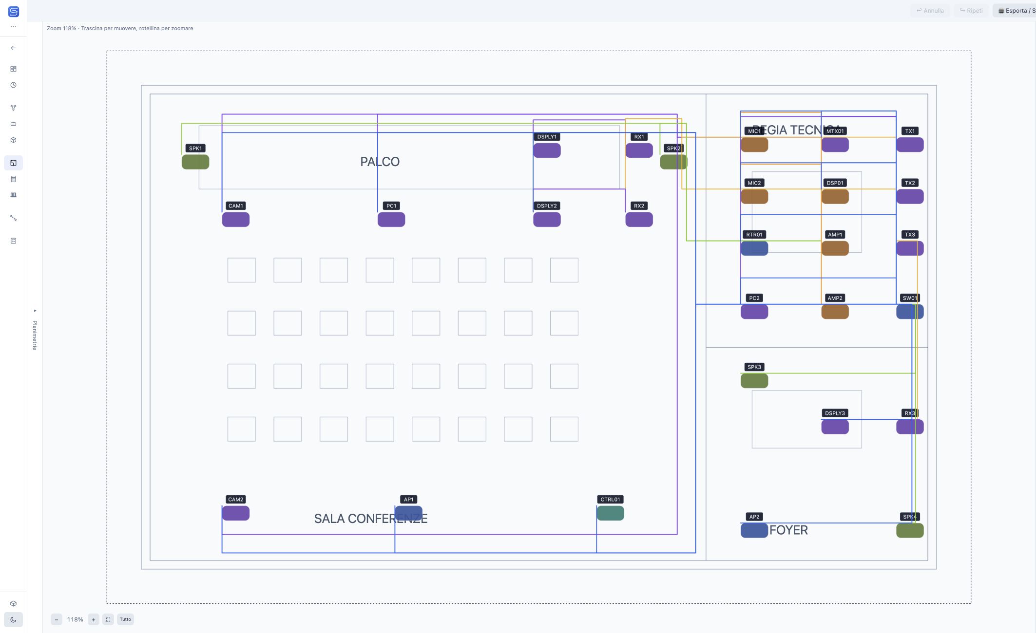
Draw cable routes, shared pathways and junctions between floors. In the demo, connections follow orthogonal segments around the perimeter, leaving the seating area clear. Estimated lengths support planning but do not replace on-site checks.
In the same project
The devices on the floor plan are the same devices as in the schematic: only the viewpoint changes, from function to location. Cables drawn on the plan are the project’s connections, so a route traced here refers to the same cable you find in the schedule.