 skemyOpen Skemy ↗
One conference room.
An AV project to explore.
Follow the work from signal distribution to installation documentation. The schematic, cable schedule, rack and floor plan describe the same system.
A fictional demonstration project. All spaces and data are fictional. Images and drawings come from the public Skemy demo, not a client installation. Screenshots and drawings show Italian interface labels.
The scenario: conference room, control room and foyer
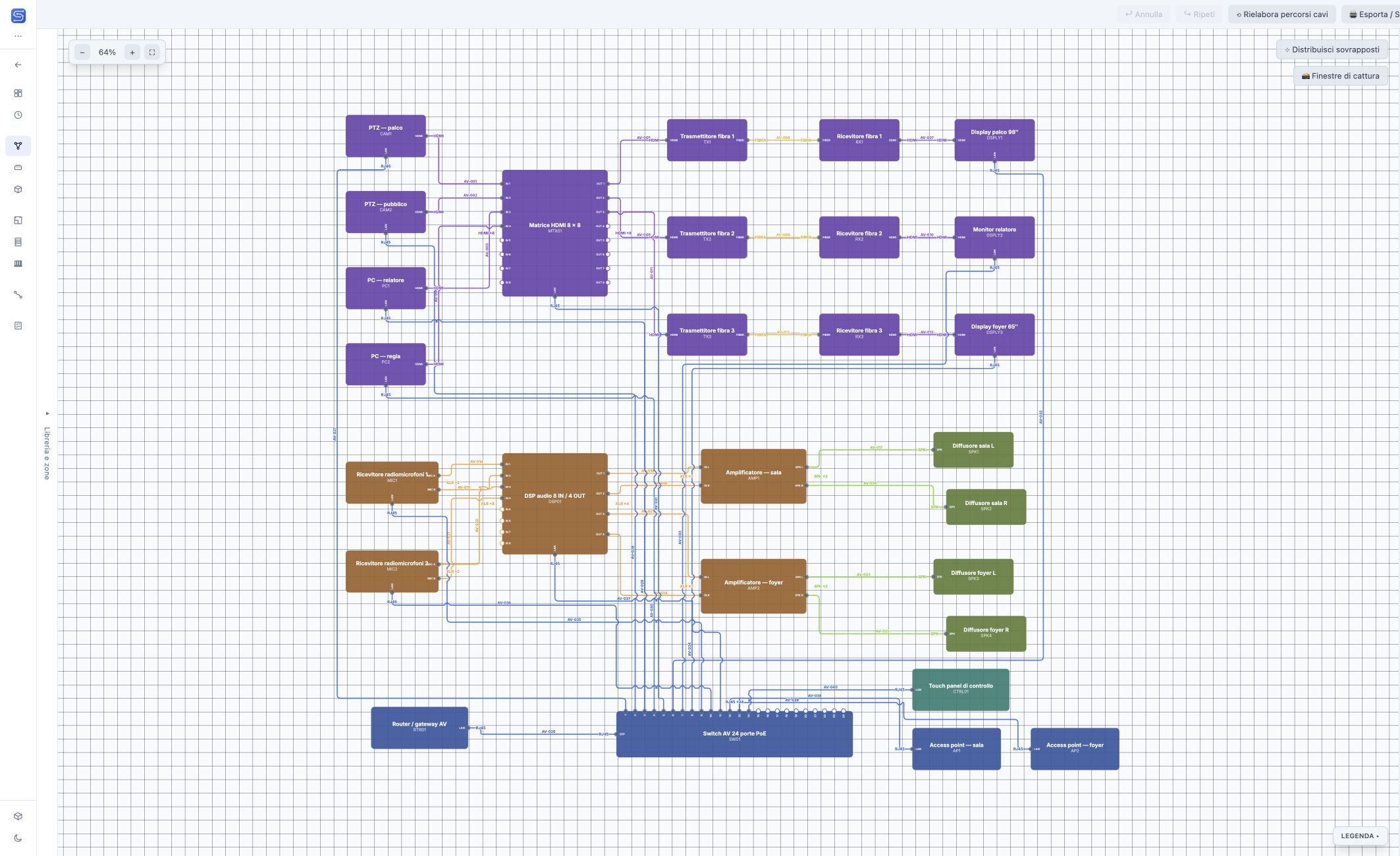
Cameras cover the stage and audience, while the presenter’s computer supplies content. The control room manages sources and distribution to the main display, presenter monitor and foyer screen. Audio passes through wireless microphone receivers, a DSP and amplifiers before reaching the speakers.
This example explains a workflow. Equipment compatibility, signal transport and lengths must be verified for every real installation.
Start with the signal path
Video sources feed an 8 × 8 HDMI matrix; fibre links continue to receivers and displays. Colours distinguish video, fibre, audio and network connections. Before installation, check the source and destination of every cable. Open vector details to inspect the drawing beyond screenshot resolution.
Explore this feature →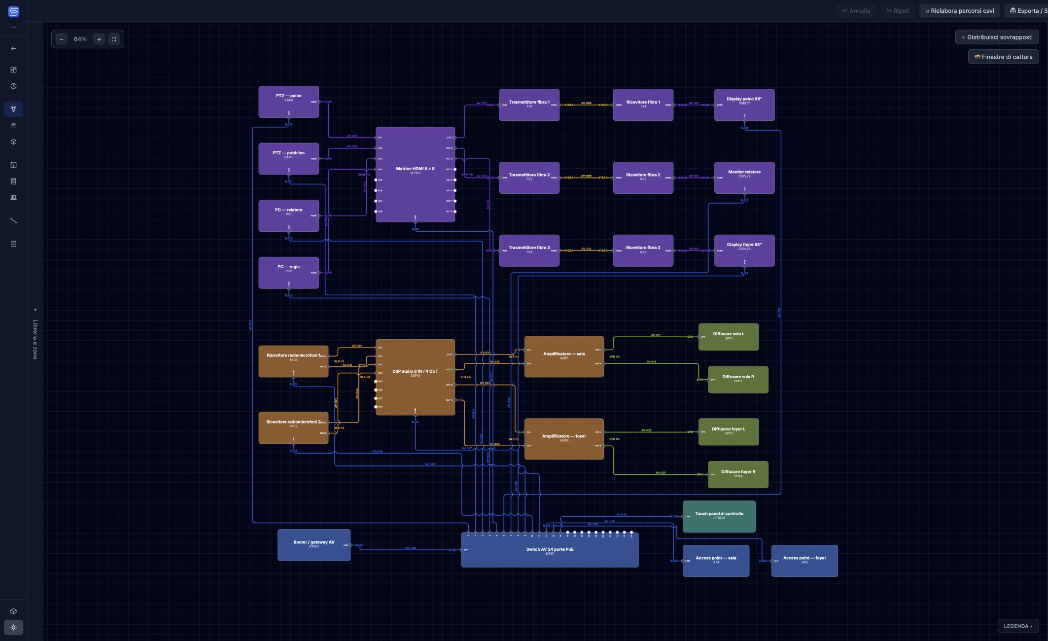
Turn connections into a working cable schedule
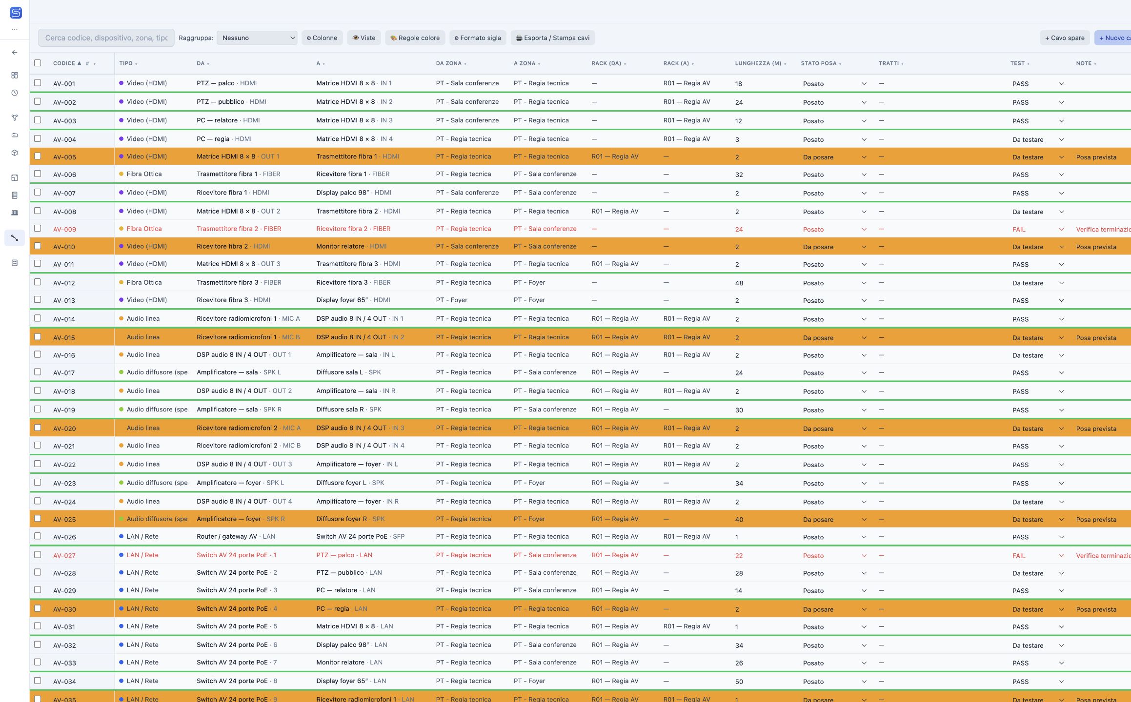
The 40 connections become schedule rows, with devices, ports, zones, racks, lengths and work status. The demo uses red text for failed tests, orange fills for pending installation and green underlines for passed tests. The first enabled rule matching a row is applied; text statuses remain the reference.
Explore this feature →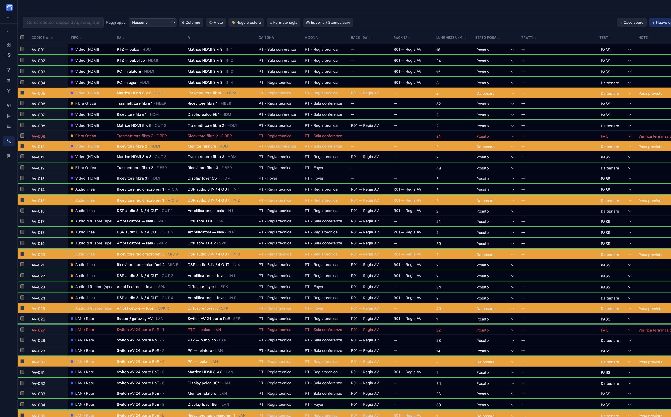
Plan the rack, including its accessories
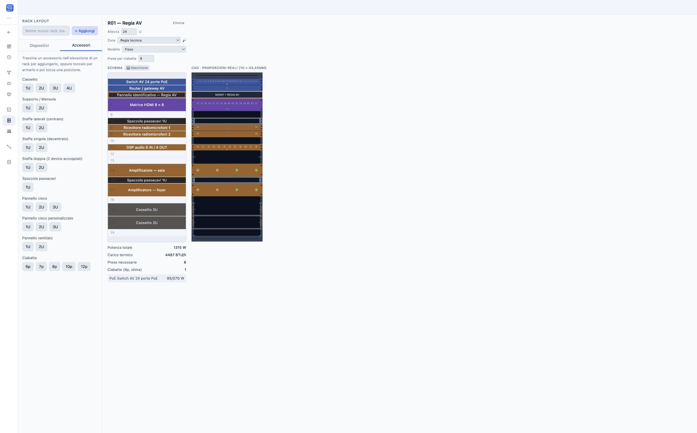
The 24 U rack houses the switch, router, matrix, receivers, DSP and amplifiers. Include the custom identification panel, cable brushes and drawers when preparing materials. Review power, heat load, outlets and PoE data alongside manufacturer specifications and installation conditions.
Explore this feature →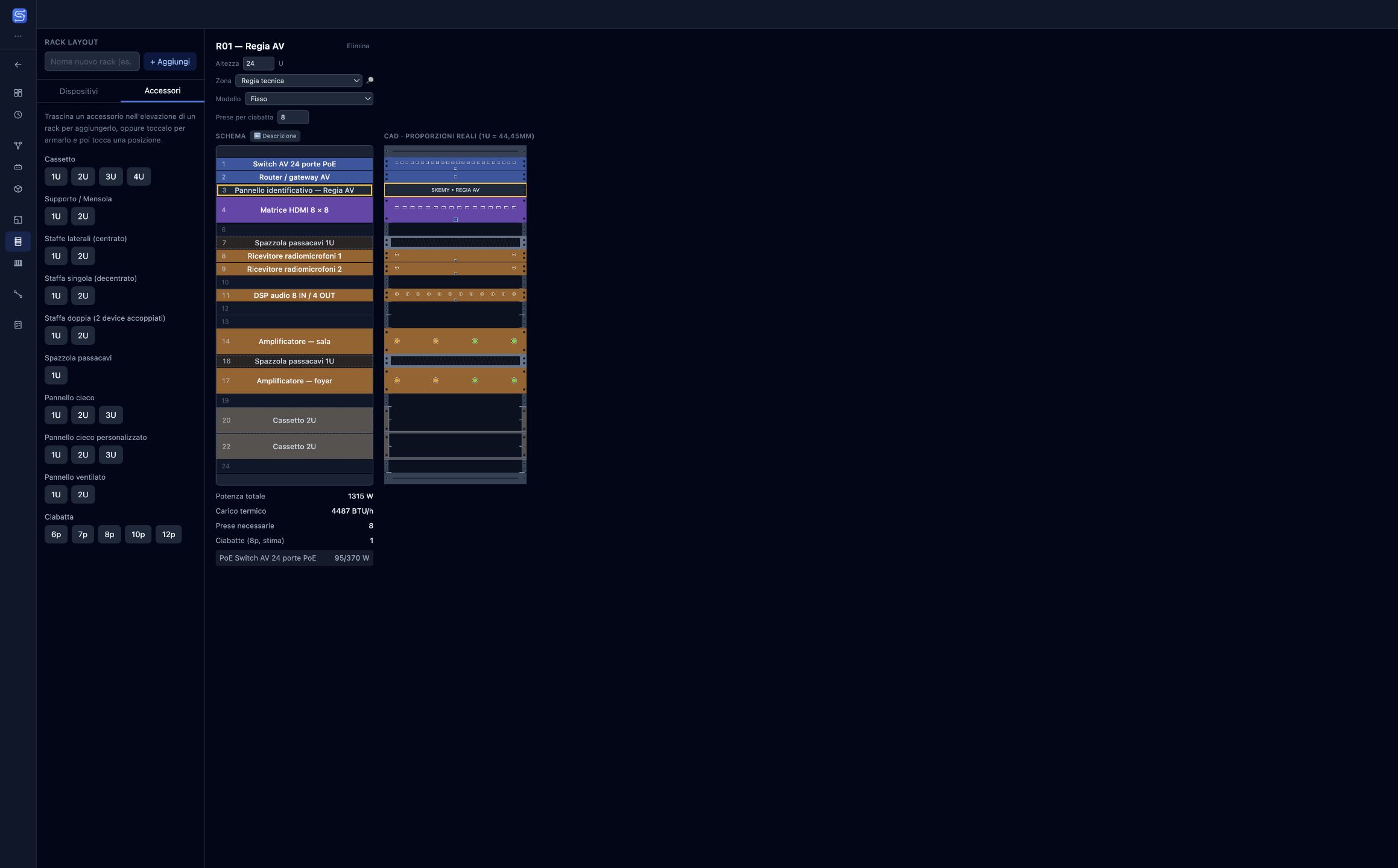
Follow routes on the floor plan
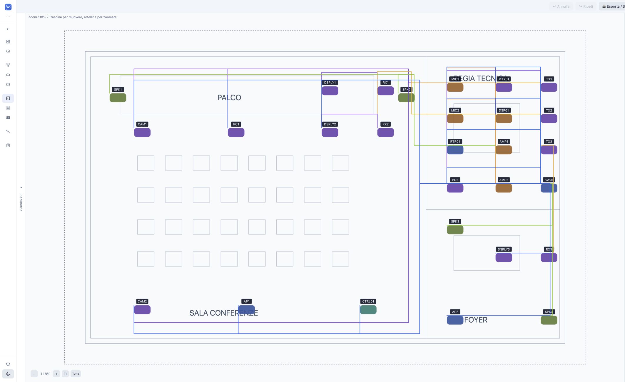
The synthetic floor plan separates the conference room, control room and foyer. Orthogonal routes follow the perimeter, leaving the seating area clear. Physical placement is independent of the signal schematic. In a real project, check scale and proportions, then keep estimated route lengths separate from measurements recorded on site.
Explore this feature →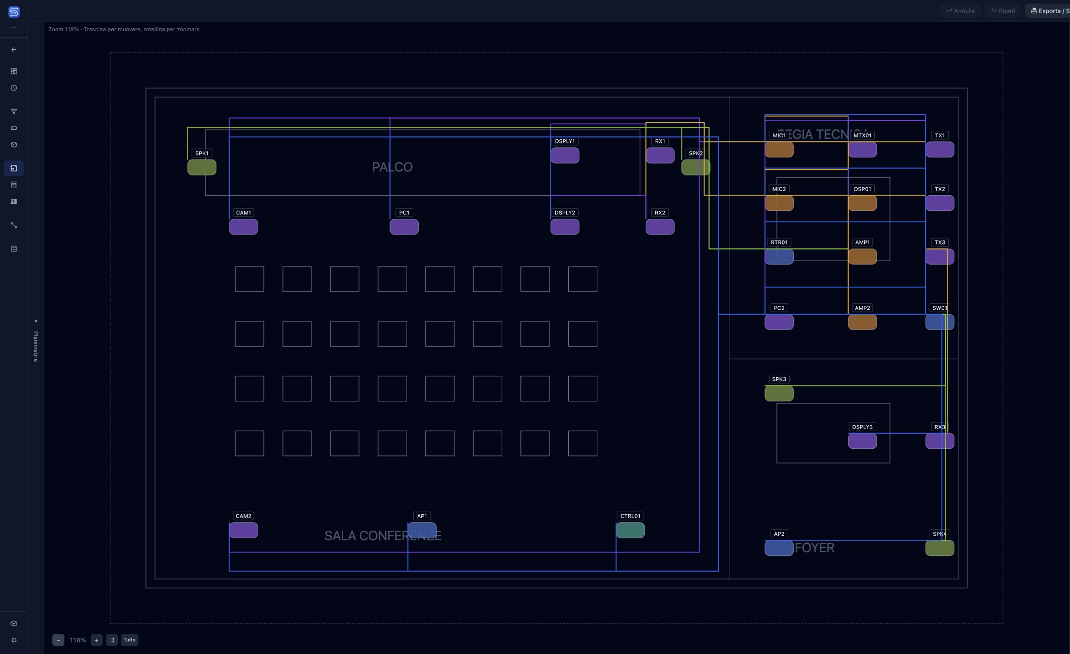
A shared reference for office and site
Installation, termination and test statuses track cable progress. Commissioning helps identify unfinished work. In shared projects, the Technician role can propose operational changes for an authorised manager to review and approve or reject.
Prepare the handover
Include a title block, date and revision in the drawings. Explore the public demo PDFs below. Vector lines and text stay sharp when enlarged.
Before using a project on site
- Check ports, signals and equipment compatibility.
- Verify drawing scale, practical routes and actual lengths.
- Check rack space, power, ventilation and maintenance access.
- Update installation and test statuses and note outstanding work.